Usage example of cloud computing service
I will explain how to use this service using examples so that you can use this service well. This service provides two types of optimization technologies: chip aspect ratio and wafer placement. If the customer's process is at the semiconductor layout design stage, use the "aspect ratio optimization". If you have already completed the layout design, use it from "Placement optimization".
Calculation of aspect ratio optimization
 If you are in the stage of designing a semiconductor layout in the future, please select " Aspect ratio optimization ".
Set 6 items in the opened input screen.
① Wafer diameter
② Orientation flat length(Notch type for zero)
③ Invalid area width
④ Chip area
⑤ Mimimum aspect ratio
⑥ Maximum aspect ratio
The initial values of ① to ⑥ can be freely rewritten. However, in order to learn how to use it, "Start calculation" is performed at the beginning with the initial values.
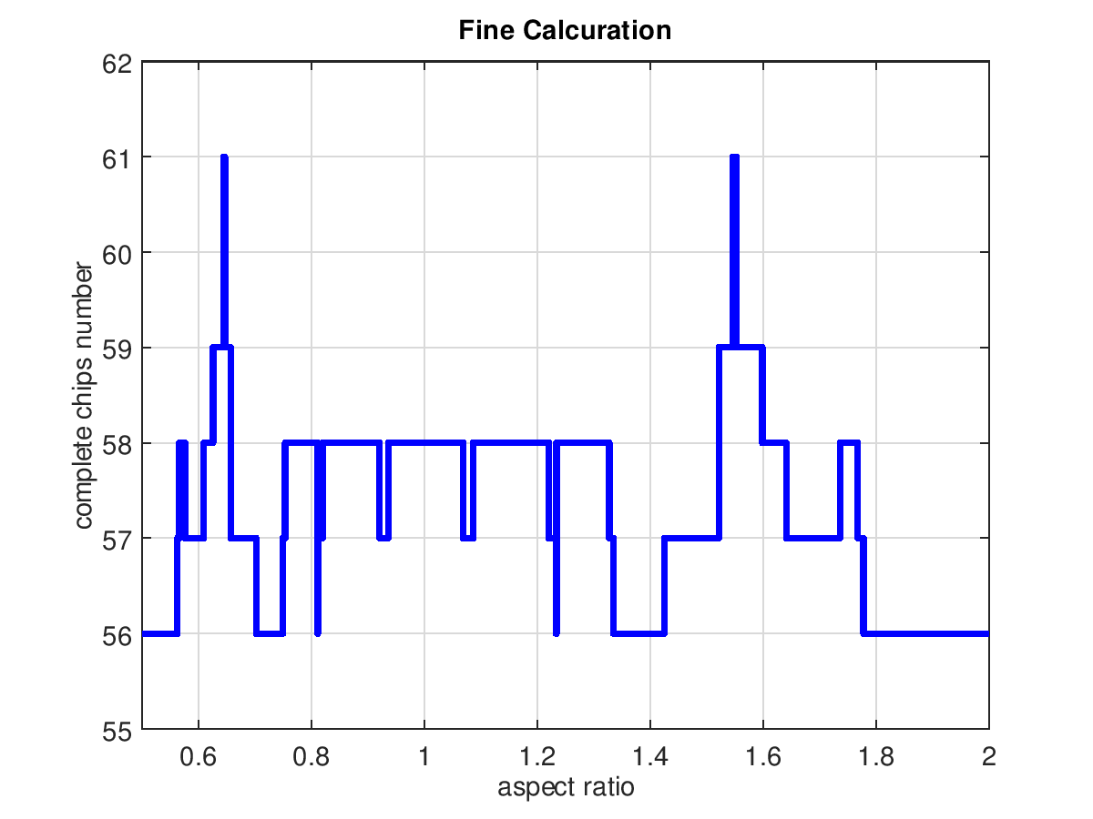
After waiting about 30 seconds, the right figure appears with the chip aspect ratio on the horizontal axis and the maximum effective chip number on the vertical axis.
By the way, the aspect ratio at which the number of effective chips is the maximum (61) is very narrow, so it is difficult to understand.
Therefore, repeat the calculation after gradually narrowing the upper and lower limits of the aspect ratio.
Then you can see that the aspect ratio is around 0.65.
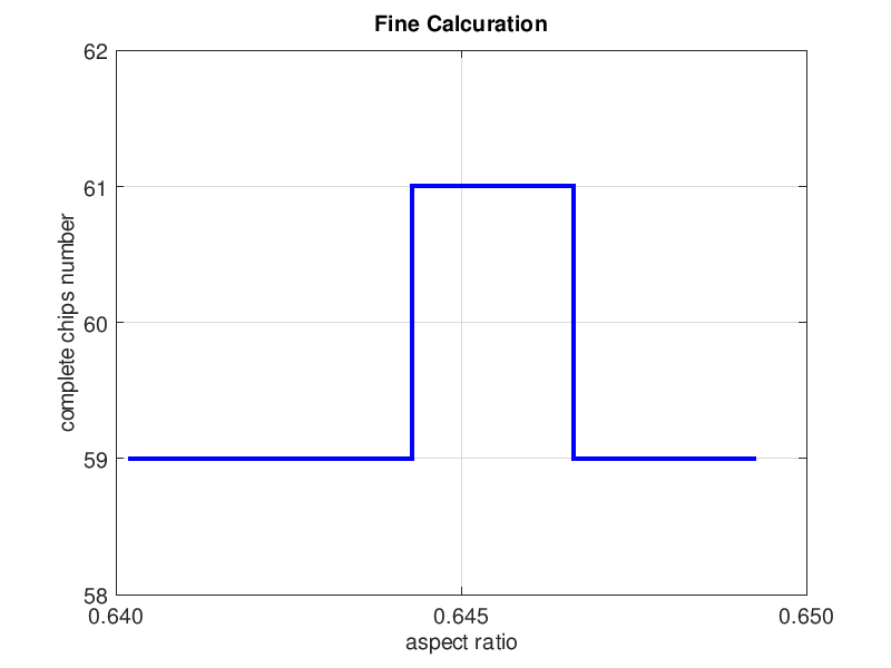
The figure on the right shows the result of recalculation with the aspect ratio changed to 0.64 to 0.65.
If the aspect ratio is 0.645, the number of effective chips will be 61.
Confirmation by wafer placement optimization
The number of effective chips becomes maximum when the aspect ratio is around 0.645.
As long as you can design the layout with that shape, there is nothing better than that.
However, if that is not possible, choose a different aspect ratio with more effective chips.
However, do not end here.
Very rarely, errors in the relationship between the aspect ratio and the number of effective chips will occur due to calculation errors.
For this reason, the number of effective chips is checked using layout optimization without relying on the relationship between the aspect ratio and the number of effective chips.
Here, it is assumed that the layout can be designed with this shape.
If the chip area is 100mm 2 and the aspect ratio is 0.645, the chip will be 8.035mm in width and 12.45mm in height.
Next, select "Placement optimization", enter the necessary items, and execute "Start calculation".
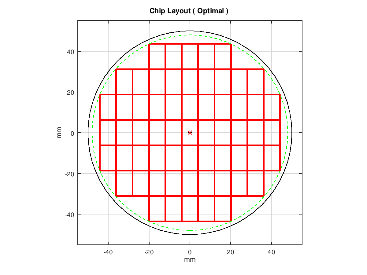
The page that appears shows the number of effective chips and the chip layout diagram shown on the right.
Finally, confirm that the number of effective chips is the expected 61, and it is complete.
On semi-precision solutions
The calculation time for aspect ratio optimization is approximately proportional to the square of the number of effective chips.
Therefore, if the number of effective chips is less than 50, you will not be bothered.
However, when the number of effective chips exceeds 50, the calculation time starts to be a concern.
If you exceed 100, you will want to interrupt the calculation.
I think that the limit of patience that can be waited is individual, but I thought that 3 minutes was the limit.
Therefore, when the wafer diameter 2 chip area is 100 or more, we decided to use the quasi-precision method.
This solution reduces the number of counting by adding to the candidate solution conditions that the center of the wafer circle is on a straight line parallel to the y-axis passing through the chip center or chip lattice point.
Although this method requires much less computation time than the precise solution, it rarely gives incorrect results.
However, there is no fear of making a big mistake if you confirm it by calculation of array optimization.
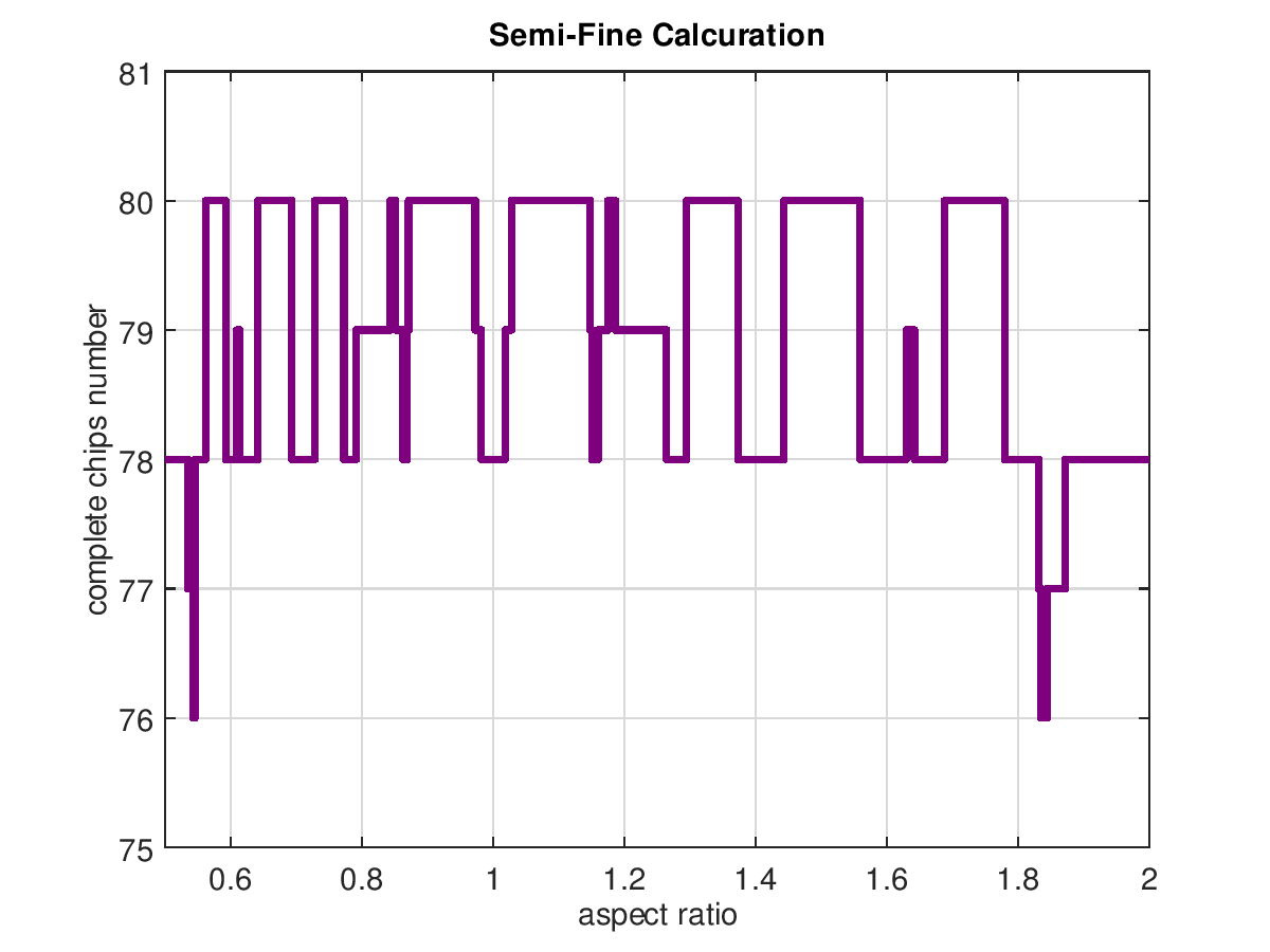
In addition, the color of the polygonal line in the figure has been changed from blue to purple and the title is also displayed as Semi-Fine Calcuration so as not to be mistaken for the precision solution.
The figure on the upper right shows only the initial value of the chip area as 75mm 2 .
About simple solution
Even with a quasi-precise solution, the computation time increases as the number of effective chips increases.
Therefore, if the wafer diameter 2 chip area is 150 or more, the quasi-precise method is not applied.
The algorithms applied here are ① to ③
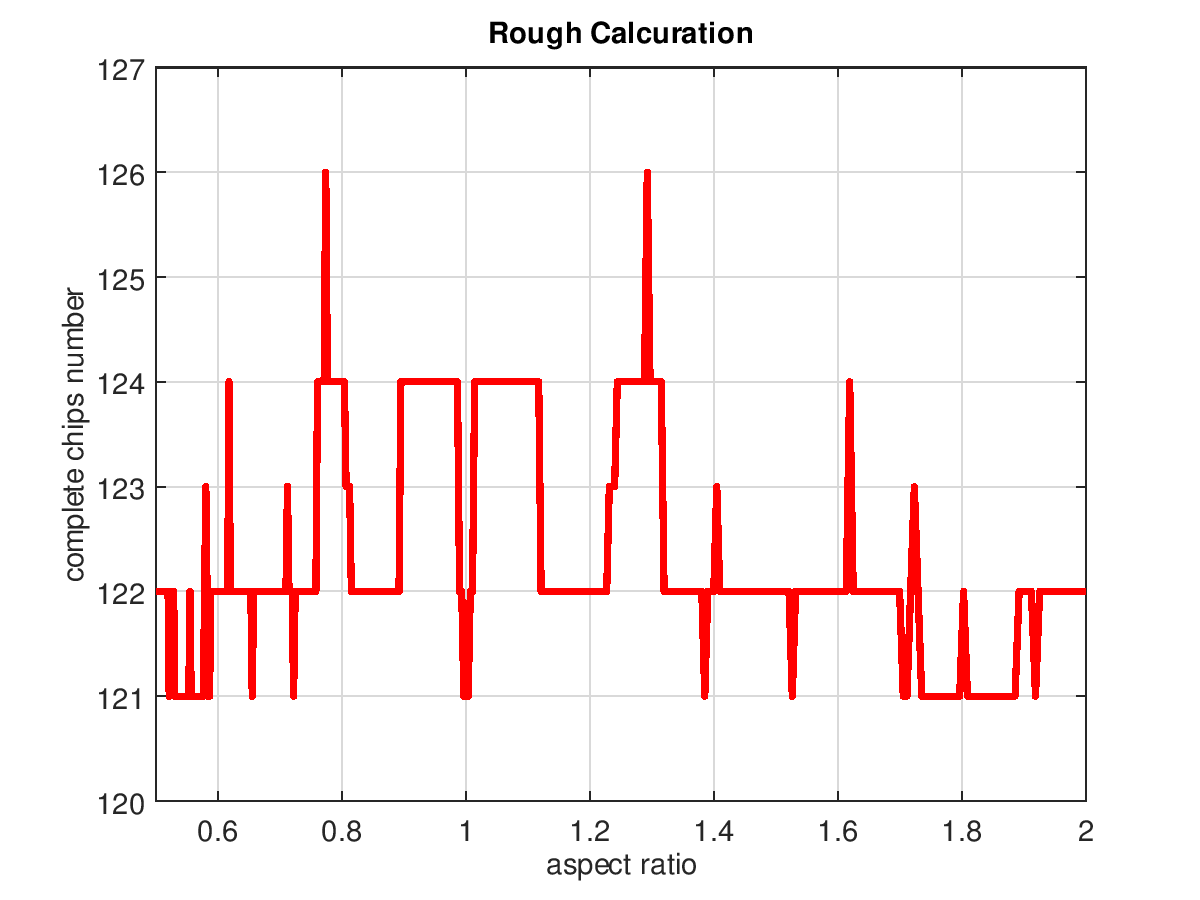
① 100 aspect ratios with logarithm equally spaced between 0.5 and 2.0 are defined.
② On the other hand, the maximum number of effective chips when the placement optimization is applied is determined by the method of the published patent (JP-A-2003-257843)
③ Connect those values in a line graph
The upper right figure shows only the initial value of the chip area as 50mm 2 .
The color of the graph is shown in red to distinguish it from other solutions.
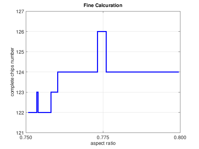
By the way, also in this case, the range of the aspect ratio at which the effective chip number becomes the maximum (126) is narrow and cannot be understood well.
In addition, the calculation method is not precise, and it seems that there is no point in narrowing the upper and lower limits of the aspect ratio.
In such cases, narrowing the aspect ratio range allows you to select a more precise calculation method.
In fact, if you change the aspect ratio range from 0.75 to 0.80 and recalculate, you will select a precise calculation method.
Click here for your opinion. Click here for questions. Feel free to help yourself.
(Update Oct 29, 2023)